How to Wire a GFCI Receptacle: Distinguishing LINE from LOAD Without Guesswork
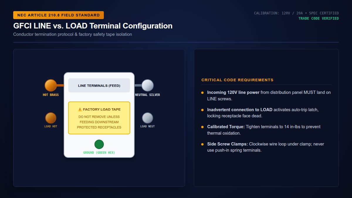
Installing a Ground Fault Circuit Interrupter (GFCI) is the single most effective defense against fatal 120-volt electric shocks in kitchens, bathrooms, garages, and outdoor circuits. Modern self-testing GFCIs monitor the current differential between the ungrounded (hot) and grounded (neutral) conductors. If as little as 4 to 6 milliamperes of current leaks to ground, an internal differential transformer collapses the field and trips the mechanical latch within 25 milliseconds.
However, over 80% of amateur GFCI installations fail code inspection for one reason: feeding the incoming 120V power into the LOAD terminals instead of the LINE terminals. On modern smart-lock GFCIs, reverse-wiring locks out the reset button, leaving the device dead and non-functional.
Step 1: Identifying the Live Line Feed Conductors
When you pull the existing receptacle from the junction box, you will typically find either one cable (two insulated wires plus bare ground) or two cables (four insulated wires plus bare grounds). If only one cable enters the box, your installation is simple: it is an end-of-run receptacle, and you will use only the LINE terminals.
If two cables enter the box, one cable brings continuous power from the panel (LINE), while the second cable continues downstream to power subsequent outlets in the room (LOAD). To distinguish them:
- Separate all wire ends so they do not touch each other or the metal box.
- Turn the breaker back on temporarily.
- Measure AC voltage with your multimeter between the black hot wire and the bare copper ground of Cable A, then Cable B.
- The cable showing 120V is your LINE feed. Turn the breaker back OFF immediately and label this cable with white electrician tape marked "LINE".
Step 2: Conductor Stripping, Pigtailing & Terminal Torque

Strip exactly 5/8 inch of insulation from each conductor using the calibrated notch on your wire strippers (14 AWG for 15A circuits, 12 AWG for 20A circuits). Inspect the copper apex: if the wire stripper nicked or scored the solid copper, cut it back and re-strip. A nicked copper conductor creates a high-resistance thermal hot spot that can reach 400°F under heavy appliance loads.
Insert the bare copper into the back-wire clamp plates:
- Hot (Black Wire): Tighten under the BRASS screw clamp on the LINE side.
- Neutral (White Wire): Tighten under the SILVER screw clamp on the LINE side.
- Equipment Ground (Bare Copper): Terminate under the GREEN hex screw on the bottom mounting yoke.
Step 3: Downstream Protection vs. Independent Receptacles
If you want this single GFCI to protect all downstream standard outlets in the room (such as a string of countertop outlets in a kitchen), remove the yellow factory tape from the LOAD terminals and connect the outgoing cable's black wire to LOAD brass and white wire to LOAD silver.
If you prefer each outlet in the room to operate independently so that a blender tripping one outlet doesn't kill the microwave, leave the yellow LOAD tape intact. Pigtail the incoming and outgoing black wires together with a 6-inch jumper to the LINE brass screw, and pigtail the neutral wires to the LINE silver screw.
Troubleshooting 3-Way Light Switches: Finding the Common Conductor
Branch Circuit Wire Gauge & Box Fill Estimator
Select your circuit parameters to verify required conductor gauge, maximum continuous wattage under the NEC 80% rule, voltage drop over distance, and minimum junction box volume.