The 3-Way Switch Diagnostic: Finding Common & Traveler Wires Without Guessing
Replacing a decorative 3-way light switch at the top of a staircase or hallway is a frequent source of homeowner frustration. You unscrew the old toggle, pull out three black and red wires, hook them up to the new Decora rocker, and suddenly the light only turns on when the downstairs switch is flipped upward.
This occurs because the DIYer assumed terminal positions on the new switch match the old switch. Terminal locations vary between manufacturers: Leviton, Lutron, and Eaton position the dark common screw in completely different corners of the switch body. What matters is never physical position — it is electrical identity.
The Anatomy of a 3-Way Circuit: Common vs. Travelers
A 3-way switch (technically a Single Pole Double Throw or SPDT switch) has three terminal screws plus a green ground screw:
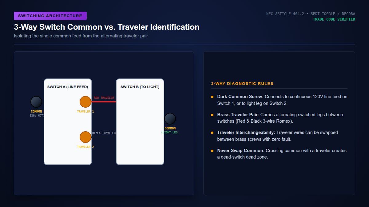
- The COMMON Terminal (Dark/Bronze Screw): This is the most important terminal. On Switch A, the common screw receives continuous 120V line power from the breaker. On Switch B, the common screw connects directly to the switch leg leading to the light fixture.
- The TRAVELER Terminals (Pair of Brass Screws): These two screws connect the 3-wire cable (14/3 or 12/3 Romex) running between Switch A and Switch B. The internal toggle mechanism simply diverts power between Traveler 1 (black) and Traveler 2 (red).
Testing With a Digital Multimeter (When Wires Are Jumbled)

If the old switch was already disconnected and you are staring at three bare wires hanging from the junction box, follow this systematic diagnostic protocol:
- Spread all three wires apart so they are not touching anything.
- Turn the breaker back ON.
- With your multimeter set to AC Volts, touch the black meter probe to a known ground (the metal box or bare copper ground).
- Touch the red probe to each of the three wires in turn:
- The single wire that reads a constant 120V regardless of the other switch's position is your COMMON wire on the feed switch.
- Mark this wire with black electrical tape. This wire MUST go to the dark screw on the new switch.
- The remaining two wires (typically red and black from the 3-wire Romex) are the travelers. Connect them to the two brass screws. Travelers are interchangeable — it does not matter which brass screw receives which traveler wire.
Converting Vintage 2-Prong Outlets: NEC 406.4(D) Grounding Retrofit
Branch Circuit Wire Gauge & Box Fill Estimator
Select your circuit parameters to verify required conductor gauge, maximum continuous wattage under the NEC 80% rule, voltage drop over distance, and minimum junction box volume.